
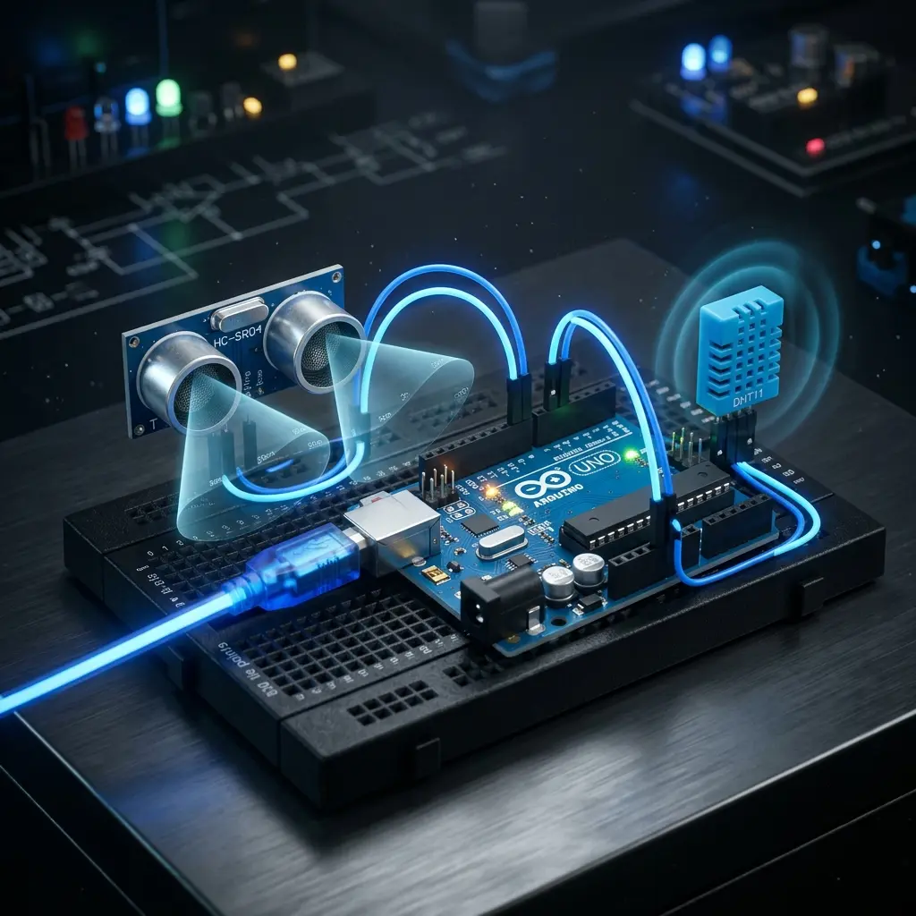
Demystifying UART, SPI, and I2C: The High-Speed Communication Protocols of Hardware
When you connect a sensor, an OLED display, or a GPS module to an ESP32 or STM32 microcontroller, how do they talk to each other? They don't have ethernet ports or HTTP REST APIs.
Instead, microchips communicate using low-level serial protocols. The three most common hardware buses in embedded systems are UART, I2C, and SPI.
At Kone Lab, we teach students to diagnose these physical waveforms using oscilloscopes and logic analyzers. Here is how they compare.
📡 1. UART: The Asynchronous Point-to-Point Wire
UART (Universal Asynchronous Receiver-Transmitter) is an asynchronous, point-to-point communication channel.
- Wires Needed: 2 wires (
TXtransmit,RXreceive) + Ground. - Clock Line: None! Both sender and receiver must pre-agree on the speed (Baud Rate, e.g., 9600, 115200 bps).
- Best Used For: Debug console logs, GPS modules, Bluetooth modules (HC-05).
[ Microcontroller ] TX --------> RX [ GPS Sensor ]
                   RX <-------- TX
                   GND -------- GND
🌐 2. I2C: The Multi-Device Addressable Bus
I2C (Inter-Integrated Circuit) is a synchronous, two-wire multi-device bus developed by Philips (NXP).
- Wires Needed: 2 wires:
* SDA (Serial Data): Carries the binary payload bits.
* SCL (Serial Clock): Pulsed by the master to synchronize data bit sampling.
- Addressing: Each peripheral chip on the bus has a unique 7-bit hardware address (e.g.
0x3Cfor OLED screens). Up to 127 devices can share the same two pins! - Pull-up Resistors: I2C is an open-drain line. Both SDA and SCL require 4.7kΩ pull-up resistors to 3.3V to function properly.
// Reading an I2C Temperature Sensor (Arduino C++)
#include <Wire.h>

#define SENSOR_I2C_ADDR 0x48

void setup() {
  Wire.begin();
  Serial.begin(115200);
}

void loop() {
  Wire.beginTransmission(SENSOR_I2C_ADDR);
  Wire.write(0x00); // Request temperature register
  Wire.endTransmission();

  Wire.requestFrom(SENSOR_I2C_ADDR, 2);
  if (Wire.available() == 2) {
    int msb = Wire.read();
    int lsb = Wire.read();
    float tempC = ((msb << 8) | lsb) * 0.0625;
    Serial.printf("Current Temperature: %.2f C\n", tempC);
  }
  delay(1000);
}
⚡ 3. SPI: The High-Speed Full-Duplex Bus
SPI (Serial Peripheral Interface) is designed for high bandwidth (typically 10 MHz to 80 MHz+).
- Wires Needed: 4 wires:
* SCK (Serial Clock)
* MOSI (Master Out, Slave In)
* MISO (Master In, Slave Out)
* CS / SS (Chip Select / Slave Select)
- Full Duplex: Data is transmitted and received simultaneously on every clock pulse.
- Best Used For: SD card storage, high-framerate TFT LCD displays, RFID readers.
📊 Summary Comparison
| Metric | UART | I2C | SPI |
| :--- | :--- | :--- | :--- |
| Wiring | 2 Wires | 2 Wires (SDA, SCL) | 4 Wires (MOSI, MISO, SCK, CS) |
| Typical Speed | Up to 115.2 kbps | 100 kbps – 3.4 Mbps | Up to 80+ Mbps |
| Multi-Device? | Point-to-Point only | Yes (127 devices by address) | Yes (1 dedicated CS wire per chip) |
| Clock Line | Asynchronous (No clock) | Synchronous | Synchronous |
Build real micro-controller circuits and IoT devices in our Embedded Systems & Circuit Prototyping Track.